
Contents
When to replace 48V power supply
Before you start
Tools required
Instructions
When to replace 48V power supply
The 48V power supply provides power for the chamber motor (that turns the paddles) and for the PCB cooling fan.
The 48V supply might need replacing if:
-
You get the message 'chamber stalled' and can see that the paddles are not moving at all
-
The PCB fan has also stopped (you can check the PCB fan RPM in the debug sensor screen)
-
You are sure that there are no issues with the mains power (for example, all three heating elements are able to heat up)
Before you start
 DISCLAIMER
The information in this document is believed to be accurate and reliable. However, the manufacturer does not give any representations or warranties, expressed or implied, as to the accuracy or completeness of such information and shall have no liability for the consequences of the use of such information. The manufacturer is not liable or responsible for any problems arising from the attempted repair. The manufacturer reserves the right to make changes to information published in this document, including without limitation specifications and product descriptions, at any time and without notice. The manufacturer's products are not designed, authorized, or warranted to be suitable for use in applications where failure or malfunction can reasonably be expected to result in personal injury, death, or severe property or environmental damage. The manufacturer accepts no liability for inclusion and/or use of its products in such equipment or applications and therefore such inclusion and/or use is for the customer’s own risk.
SAFETY INSTRUCTIONS
-
Make sure the roaster is turned off before starting any maintenance work.
-
The power cord must be unplugged or the roaster fully isolated from the electrical supply before removing any panels.
-
Read the instructions in full before starting work, and follow the steps as instructed below
Tools required
- Flat-head screwdriver, coin, or similar to open front door
- 2.5 mm hex key
- 3 mm hex key
- Narrow-nosed pliers
- Philips head screwdriver
- 8 mm spanner or wrench
- Small flathead screwdriver or other pointed tool
Instructions
Open the front door and remove the both side panels and top panel
See the guide here.
Remove the bean cooler fan
See the guide here.
Remove the power supply
Start by moving the bean cooler out of the way. The cooler is mounted on a hinge; pull it towards you to access the parts behind.
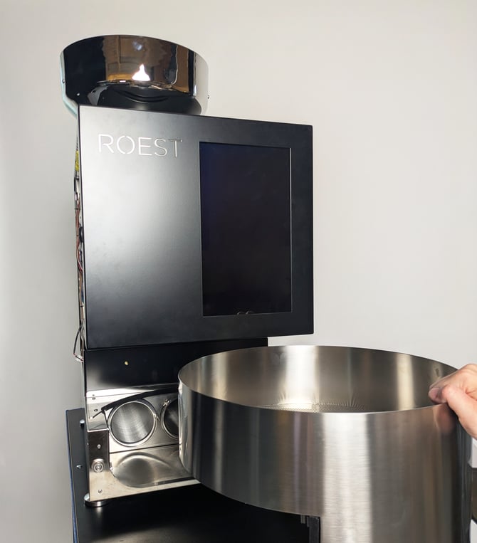
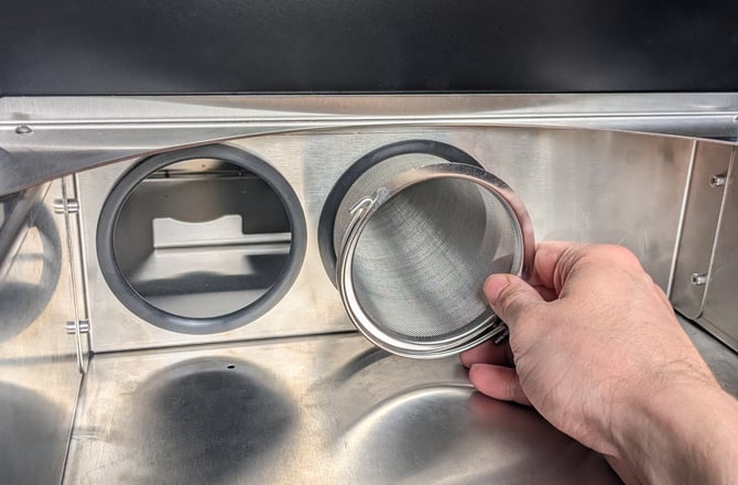
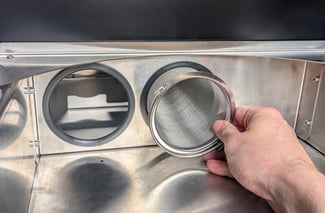
Remove the bean cooler filters and set aside.
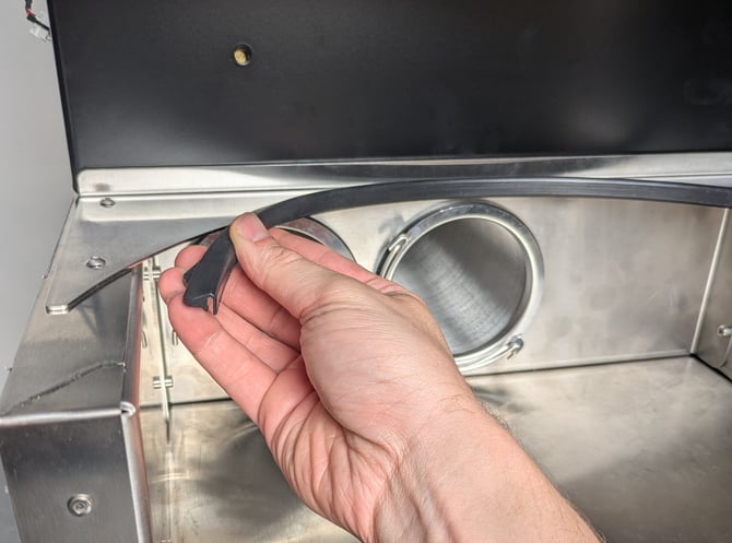
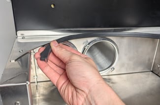
Remove the lip gasket around the top of the bean cooler and set aside.
With the bean cooler filters removed, you can now access the bolt at the back of the lower enclosure cover. Loosen the bolt with the 3 mm hex key.
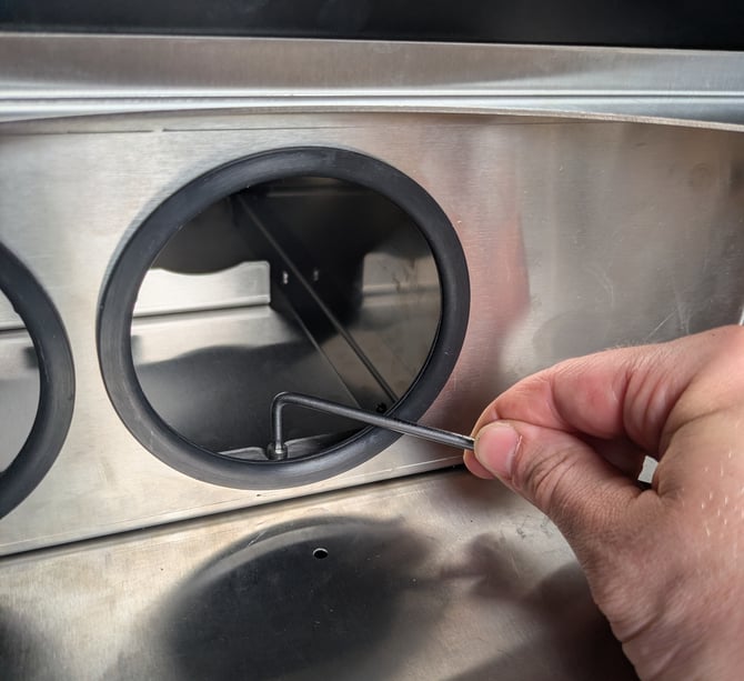
Remove the four bolts at the sides of the cover with the 3 mm hex key.
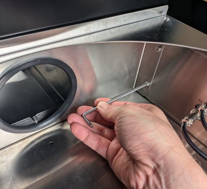
Remove the cover to access the inside of the lower enclosure.
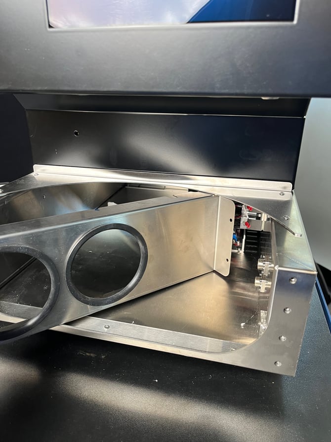
Use the Phillips head screwdriver to loosen the screws that fasten the wires to the front of the power supply. Disconnect the wires.
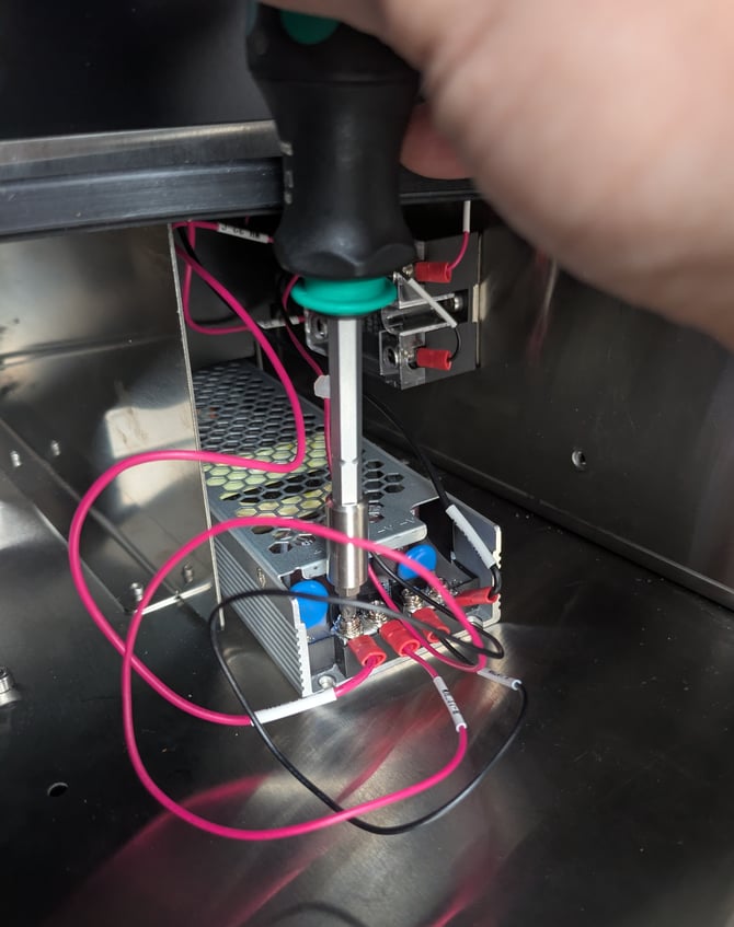
With a 2.5 mm hex key, remove the two bolts holding the power supply in place.
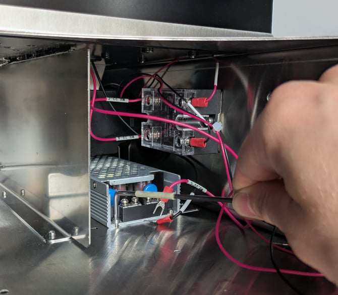
Look underneath the roaster and identify the two bolts that hold the power supply in place at the rear. These bolts have flat faces on the shank to allow them to be turned from beneath the roaster.
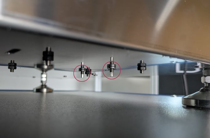
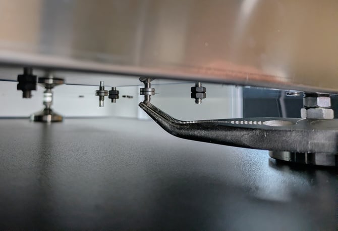
Loosen the bolts using the narrow-nosed pliers.
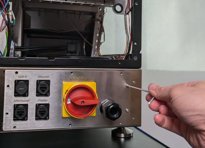
Use the 2.5 mm hex key to remove the bolts securing the power switch access panel.
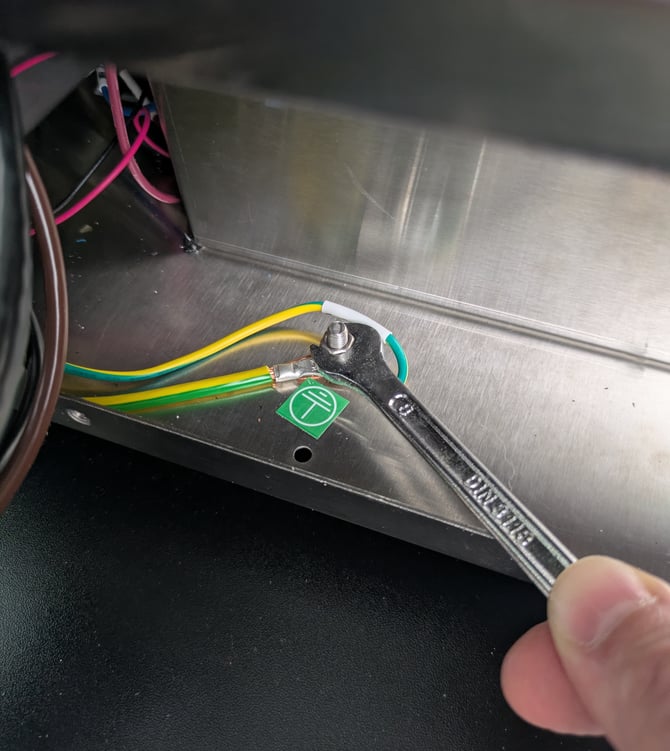
Open the panel and use an 8 mm spanner to remove the two nuts securing the two ground wires to the earthing point. Disconnect the wire labeled 'WH_33'. Leave the other wire connected.
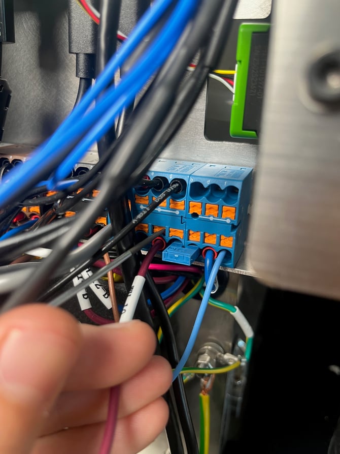
Locate the terminal blocks on the back of the machine and find the two wires labelled WH_10 (red) and WH_11 (blue). Depending on the model of your machine, the wire labels may have additional letters after the name, for example in the picture below it is labelled WH_10-A.
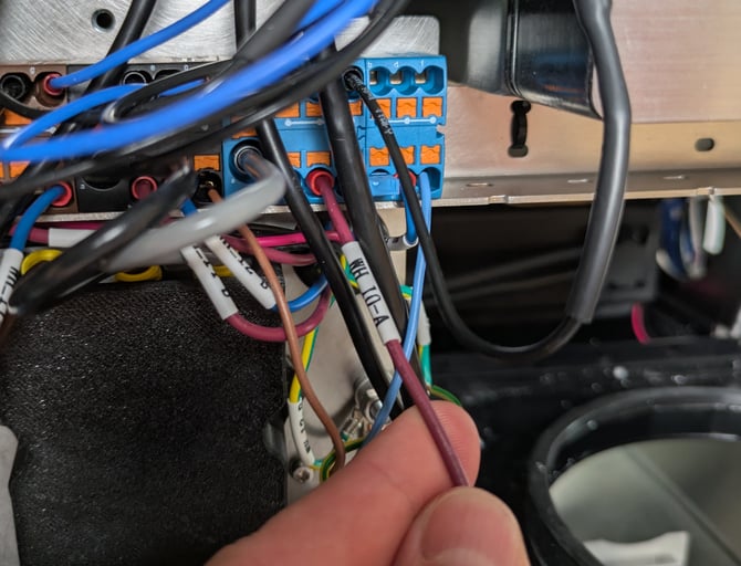
Make a note (or take a photo) of which slots in the terminal block each wire is connected to. Depending on the version of your machine, the wires may be connected to different blocks.
With a small flat-head screwdriver or pointed tool, disconnect the wires. Push the orange button all the way in and gently pull the wire out.
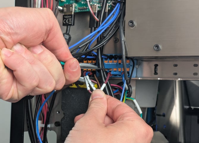
Pass the wires down through the gap into the lower enclosure below.
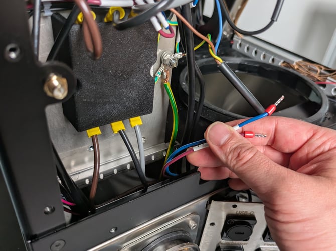
Pull the power supply out from the front of the machine.
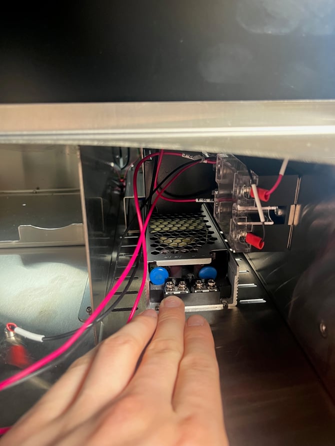
Remove the plastic cover over the terminals at the back of the power supply.
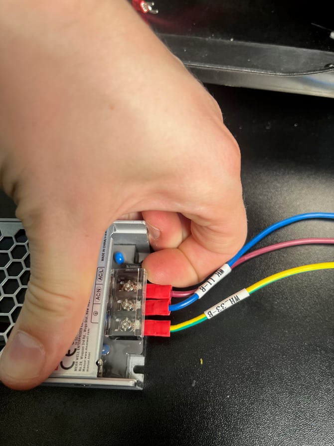
Make a note of how the wires are connected. The red wire is connected to the live, marked AC/L. The blue wire is connected to the neutral, marked AC/N. The green and yellow wire is connected to the earth, marked with the earth symbol ⏚.
Use the Phillips head screwdriver to loosen the terminal screws and disconnect the wires.
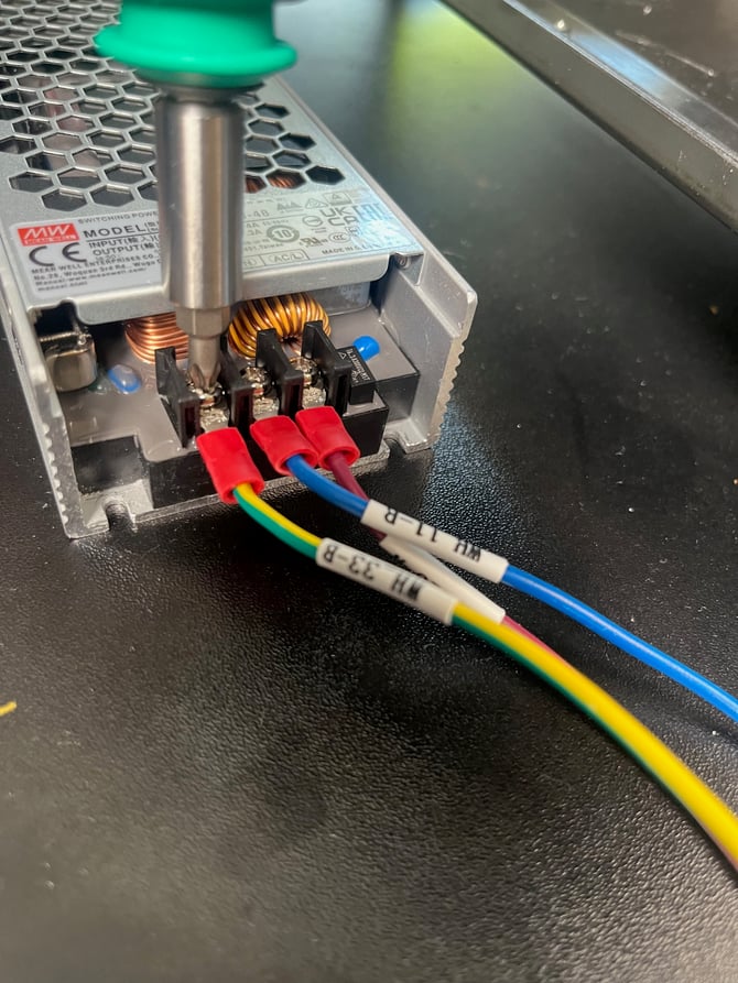
Fasten the wires to the same positions on the new power supply and reinstall the plastic cover. Make sure to match the original position of the wires.
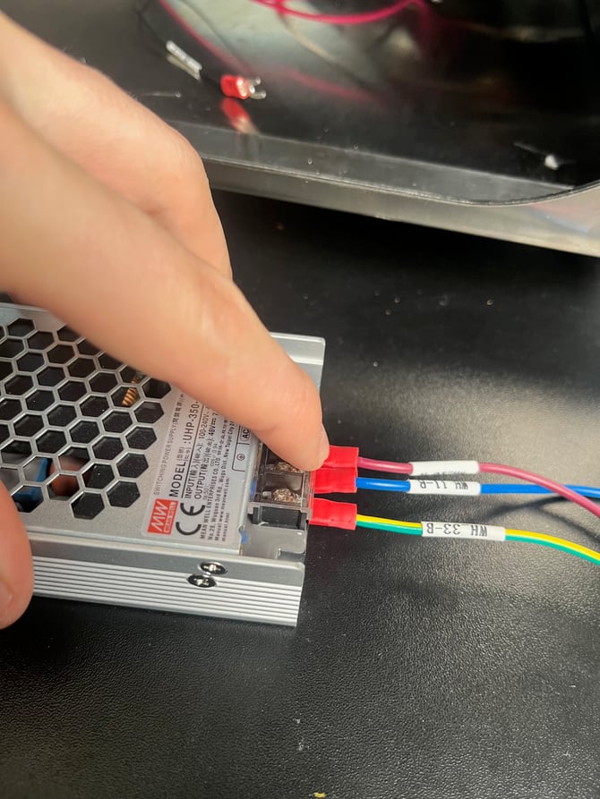
Position the new power supply in the machine, feeding the wires through to the back of the machine first. Line up the power supply with the bolts that hold it in place at the rear, and slide it into position so that the bolts go into the slots at the back of the power supply.
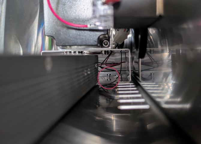
If it is in the right place, the slots at the front of the power supply will line up with the threaded holes in the base of the machine.
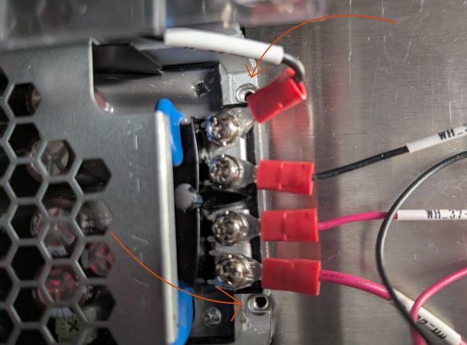
Secure the power supply with the bolts at the front, using the 2.5 mm hex key.
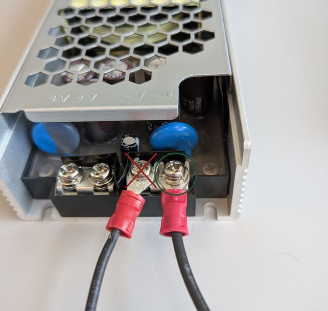
Reconnect the wires at the front. Attach the red (live) wires to the two terminals marked +V and the black (neutral) wires to the terminals marked -V.
Ensure the fork on the cable passes underneath the clamp washer before tightening the screw. In the picture below, the terminal marked with a cross ❌ is connected incorrectly.
Reach into the lower enclosure through the access panel at the back to fish the wires out from the back of the power supply. A long tool, such as needle nosed pliers, tweezers,or even a screwdriver may help here to grab the wires.
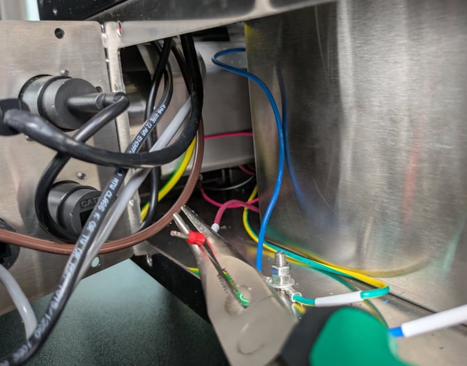
Connect the ground wire to the earthing point and use tighten the two nuts to secure it in place. Tighten the lower nut first, then tighten the upper nut on top to hold it securely.
Pass the live and neutral wires back up through the gap at the back below the terminal blocks.
Reconnect the wires to the terminal blocks, making sure to connect them to the same slots they were in originally. Do not use the photo as a guide to which slots to use — different versions of the machine will have different configurations.
To reconnect the wire, push the orange button in with a pointed tool, insert the wire into the slot, and release the button. Gently pull on the wire to ensure it is properly locked in position.
Close the power switch access panel and secure with the button-head screws.
At the front of the machine, make sure the cables are tucked away inside the compartment on the right hand side, before putting the lower enclosure cover back into position.
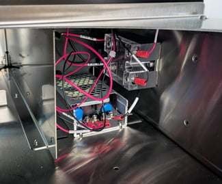
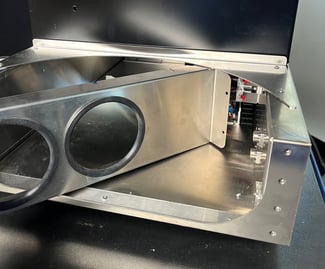
Secure the cover in position with the four bolts at the sides, and then tighten the bolt behind the cover.
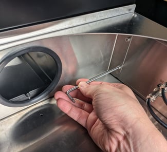
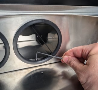
Reinstall the bean cooler filters and replace the bean cooler lip gasket.
Finish up
Reinstall the bean cooler fan.
Replace the panels and secure with bolts.
Push the bean cooler back into position.